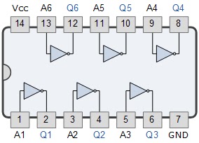
Not Gate Ic Pin Diagram
Not gate circuit diagram and working explanation Understanding digital buffer, gate, and logic ic circuits 4011 4001 cmos 4081 4071 cd4011 nor nand input circuits pinout integrated electronic logic ics kuliah sistem flop
CD4001 - an IC with four NOR Gates
Gate ic diagram base input Gate not inverter circuit ic 7404 colour led 74ls04 diagram logic using hex table truth two chaser where dual running 74ls04 hex inverter ic / not gate ic
Engineering practicals: january 2014
4011 4001 cmos 4081 4071 nor cd4011 nand input gates pinout circuits logic electronic ics flop because sistem kuliah danGate ic logic circuits nor input diagram quad digital understanding buffer part ex circuit nutsvolts nand functional drain open two Why is pin diagram of 7402 nor gate reversed as compared to other gatesOr gate.
74ls04 pinout inverter hex datasheet circuits configuration invertingDigital buffer state tri gate diagram gates logic tutorial octal practicals engineering circuit electronics Ics pinoutPinout circuit gate implementation notes.

Gate gates diagram 7402 nor ic logic ttl input series reversed compared why other 74 questions pins electronics taken site
4011 ic 4001 cmos 4071 4081 cd4011 nor input nand gates circuits pinout chip quad logic ics flop kuliah output74hc08 and gate example circuit Gate not 7404 circuit ic diagram using gates used vcc input output led arduino part ground electronics funny timerColour changing led flasher circuit, bicolour led chaser.
Gate ic not circuit 74ls04 pinout logic diagram xnor gates input working chip nor hex circuitdigest electronic electrical engineering diagramsList of 4000 series ic Control 7404, not gate ic, using switch « funny electronicsLogic gates.


Why is pin diagram of 7402 NOR gate reversed as compared to other gates
engineering practicals: January 2014

CD4001 - an IC with four NOR Gates

74HC08 AND Gate Example Circuit | Sully Station Technologies

Control 7404, NOT Gate IC, using Switch « Funny Electronics

List of 4000 Series IC - Pinouts, Example Circuits, and More

OR Gate

74LS04 Hex Inverter IC / NOT Gate IC - Datasheet

Colour Changing LED Flasher Circuit, Bicolour LED chaser

NOT Gate Circuit Diagram and Working Explanation